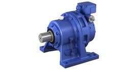
Cyclo® 6000 Speed Reducer
Our best-selling reducer with high strength and reliability, thanks to the unique Cyclo® mechanism.
- With a long history of quality and reliability, the Cyclo® has become synonymous with the term speed reducer.
- Unique Cyclo® mechanism results in high durability and extended operating life.
- Wide variety of products available that take advantage of this technology.
- Select the best product to meet your needs from a wide range of capacities and reduction ratios.
| Output Shaft | Solid shaft |
| Output Shaft Direction(s) | Any Mounting Direction (horizontal, vertical downward, vertical upward) |
| Mounting Style | Foot Mount, Flange Mount, Case Mount |
| Frame Size | 56 sizes (output stages) |
| Reduction Ratio | 2.5:1 - 658503:1 |
| Rated Torque | Up to 603,620 lb-in (68200 N⋅m) |
Product Features
Break-Resistant Gears
Unlike a regular involute tooth-gear, the "cycloidal disc," which is the gear for the Cyclo® Reducer, features a distinctively smooth curve.
A unique circular-arc tooth profile is also used for the internal gear. The smooth rolling contact that prevents tooth breakage results in a durable gearbox with a long service life. (Some low reduction ratio models use helical gears and planetary gears.)
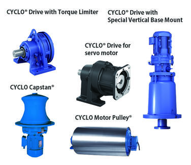
Products for Various Applications
A variety of products are offered to suit any application.
You can choose the product that best meets your specific application needs.
CAD / Configure
Select your level of product detail:
Learn more about our CONFIGURATOR TOOL:
FAQ
Do you have questions about the Cyclo Drive? Below are some of our most commonly asked questions or you can view our Support area under Knowledge for more frequently asked questions and answers.
What is the principle of Cyclo® technology?
Cyclo® is a type of internal planetary gear. The planetary gear has cycloidal-shaped teeth. All torque-transmitting parts roll, not grind. Unlike the normal involute teeth with limited contact points, a Cyclo has two-thirds of its reduction components in contact at all times. Multiple teeth share the load, so therefore the Cyclo® is not susceptible to tooth breakage.
Can the Cyclo® Drive be mounted vertically?
Models having an "N" after the nomenclature symbol "C (Cyclo)," are universal mounting models that can be mounted in any direction . However, when there is an "H (horizontal)," "V (vertical with slow speed shaft downward)" or "W (vertical type with slow speed shaft upward)," after the "C," the unit cannot be mounted in any direction other than the one specified.
Are mounting bolts included with the Cyclo®?
Mounting bolts are not included. Refer to the maintenance manual for mounting bolt specifications.
What should I do for the maintenance of small models?
Cyclo frame size 606 to 612# are called “MF: Maintenance Free.” Grease replenishment is not required for normal operating conditions, and grease fittings are not utilized. Sumitomo recommends overhaul and grease change at 20,000 hours or 4-5 years. However, when the Cyclo uses special grease for high or low ambient temperature and grease fittings are installed, then grease replenishment and grease changes are required according to the appropriate factory schedule.
What is the allowable input speed of the Cyclo®?
Generally, Cyclo® Drives allow for input at 3600r/min for up to 3HP, 6:1 to 87:1 ratio. For more than 3HP, it varies depending on frame size and reduction ratio. Many Cyclo models can accept input speeds of up to 3,600 RPM. However, the maximum allowable input speed is dependent upon the model number and the reduction ratio.
In the Cyclo® catalog, there are more than two reducer types indicated for one motor input capacity. Which reducer model should I choose?
Selection should be made based on required Service factor. The Service Factor value depends on the load characteristics and operation time for the customer’s application.
What is the largest reduction ratio actually available with a Cyclo®?
Theoretically any combination is available by multiplying single reduction ratios: 6, 8, 11, 13, 15, 17, 21, 25, 29, 35, 43, 51, 59, 71, 87, and 119:1.
What are service factors and how are they used?
In general, reducers and gearmotors are rated for specific conditions and operating requirements of the application by the use of AGMA-defined Service Factors. There are three AGMA load classifications for reducers: uniform (U), moderate shock (M) and heavy shock (H), and three AGMA load classifications for gearmotors: I, II, and III. Refer to our catalog for a list of AGMA load classifications. These Service Factors are used in the product selection process to adjust for the specific conditions and operating requirements of your application.

