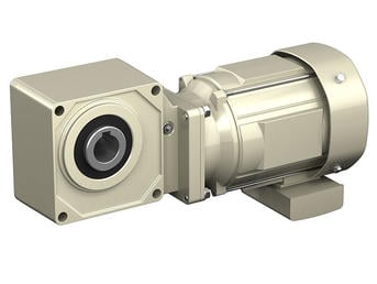
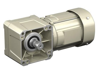
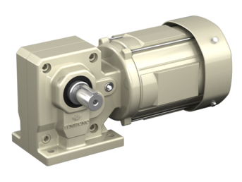
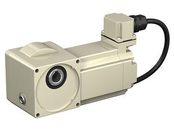
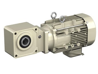
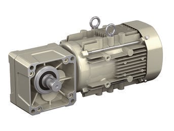
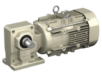
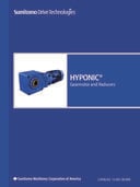
HYPONIC® Gearmotor
Right angle shaft gearmotor, with a motor range of 1/8 to 15 HP
- Maintenance-free grease lubrication eliminates oil changes
- A wide range of choices ( 1/8 to 15 HP ) to accommodate all types of uses.
- Modular design allows for multiple gearheads and motor combinations for increased service factor.
- A variety of industry packages and options are available, including grease lubrication, antibacterial coating, waterproofing, and low-temperature requirements.
| Output Shaft | Hollow shaft, Solid shaft |
| Output Shaft Direction(s) | Any Mounting Direction |
| Mounting Style | Shaft mount, Foot mount, Flange mount |
| Frame Size | 12 sizes |
| Reduction Ratio | 5:1 - 1440:1 |
| Capacity | 1/8 to 15 HP |
| Motor Types | Three phase, premium efficiency, high efficiency, for inverters, single phase, outdoors, waterproof, increased safety, compliant with overseas standards |
Product Features
CAD / Configure
Select your level of product detail:
Learn more about our CONFIGURATOR TOOL:
What should be considered when connecting to the Hyponic® shaft?
When mounting a pulley, sprocket, or sheave, mount as close to the unit housing as possible; never mount beyond the midpoint of the shaft projection to avoid undue bearing load and shaft deflection. Never overtighten belts or chains. Careful and accurate installation is essential for best results and trouble-free operation. Before installing, the shafts should be checked to make sure they are parallel and level. After mounting, alignment should be checked with a string or straight edge held against the sides of the sprocket or pulley base. Couplings should be properly aligned to the limits specified by the manufacturer. Check alignment prior to initial startup on coupled Hyponic® units.
What is the rotation of the Hyponic shaft?
The direction of shaft rotation on Hyponic reducers varies according to frame size and ratio. Please refer to the Appendix in our catalog for specific data on the shaft rotation of various models.
What is the required tolerance of the shaft to be used on the Hyponic®?
Shaft tolerances will depend on the type of load and shock load of the application. Shaft tolerance recommendations are included in the Appendix of our catalog.
Do you supply a torque arm? At what position should it be mounted?
A torque arm assembly is offered as an option. The standard torque arm assembly and standard mounting positions are shown in the Appendix of our catalog.
What is the standard mounting of the Hyponic®?
The Hyponic® is standardly supplied as a shaft mount with a keyed hollow bore. Options are available for a solid shaft with feet and a flange mounting configuration. Since the Hyponic® is grease lubricated as standard, it can be mounted in any position
without modifications.
What are the thermal limitations of the Hyponic®?
The Hyponic® speed reducer, by virtue of its smooth, almost frictionless operation (unlike traditional helical gears), has a thermal rating that far exceeds its mechanical capacity and all but eliminates the conventional limitations due to heat.
What are the standard input speeds?
In general terms, the speeds are 1750 and 1450 RPM. The selection tables in our catalog are based on 1750 RPM. The reducer selection tables show ratings at 1750 RPM for Quill models, and 1750 and 1450 for C-face models.
How can I be sure that the reducer can withstand periodic excessive overloads?
Hyponic® speed reducers provide 250% momentary intermittent shock load capacity. For applications with shock loads greater than 250%, consult a Sumitomo Application Engineer.
What do I do if my application has particularly severe operating conditions?
The standard ratings for Hyponic® are based on 10-hour daily service under conditions of uniform loads (equivalent to AGMA service factor 1.0). By following the product selection process outlined in our catalog, you will determine and apply the Service Factors to compensate for severe operating conditions.
What are service factors and how are they used?
In general, reducers and gearmotors are rated for specific conditions and operating requirements of the application by the use of AGMA-defined Service Factors. There are three AGMA load classifications for reducers: uniform (U), moderate shock (M) and heavy shock (H), and three AGMA load classifications for gearmotors: I, II, and III. Refer to our catalog for a list of AGMA load classifications. These Service Factors are used in the product selection process to adjust for the specific conditions and operating requirements of your application.

Enhance Your Industrial Operations with Sumitomo
Our industrial solutions set the standard in durability, efficiency, and innovation. Engineered to handle the toughest challenges, we are the reliable choice for your operations.
